Manufacturing Instruction for BaRiFlex

Summary

  • This is the design instruction for BaRiFlex. The estimated 3D printing time is one day, and the assembly time is under an hour.
  • As the first step, purchase all the items from here
  • Download the 3D printing parts here and print all parts.
  • Follow the 'Electronic Instruction' on this page to complete the motor wiring setup with calibration.
  • Follow the 'Design Instruction' on this page and assemble all the parts for BaRiFlex.
  • Refer to the BaRiFlex code here. Now you are ready to use BaRiFlex!
  • Contact us at goochul@utexas.edu if you have any questions.
  • Electronic Instruction

    Text Instruction
  • Use the soldering iron and wire cutter, connect the GL60 encoder pins to the small cables for the ODrive motor driver as shown in Encoder wiring diagram.
  • Connect the 24 power supply and A,B,C phase motor cables to the ODrive motor driver as illustrated in Power Cable Diagram.

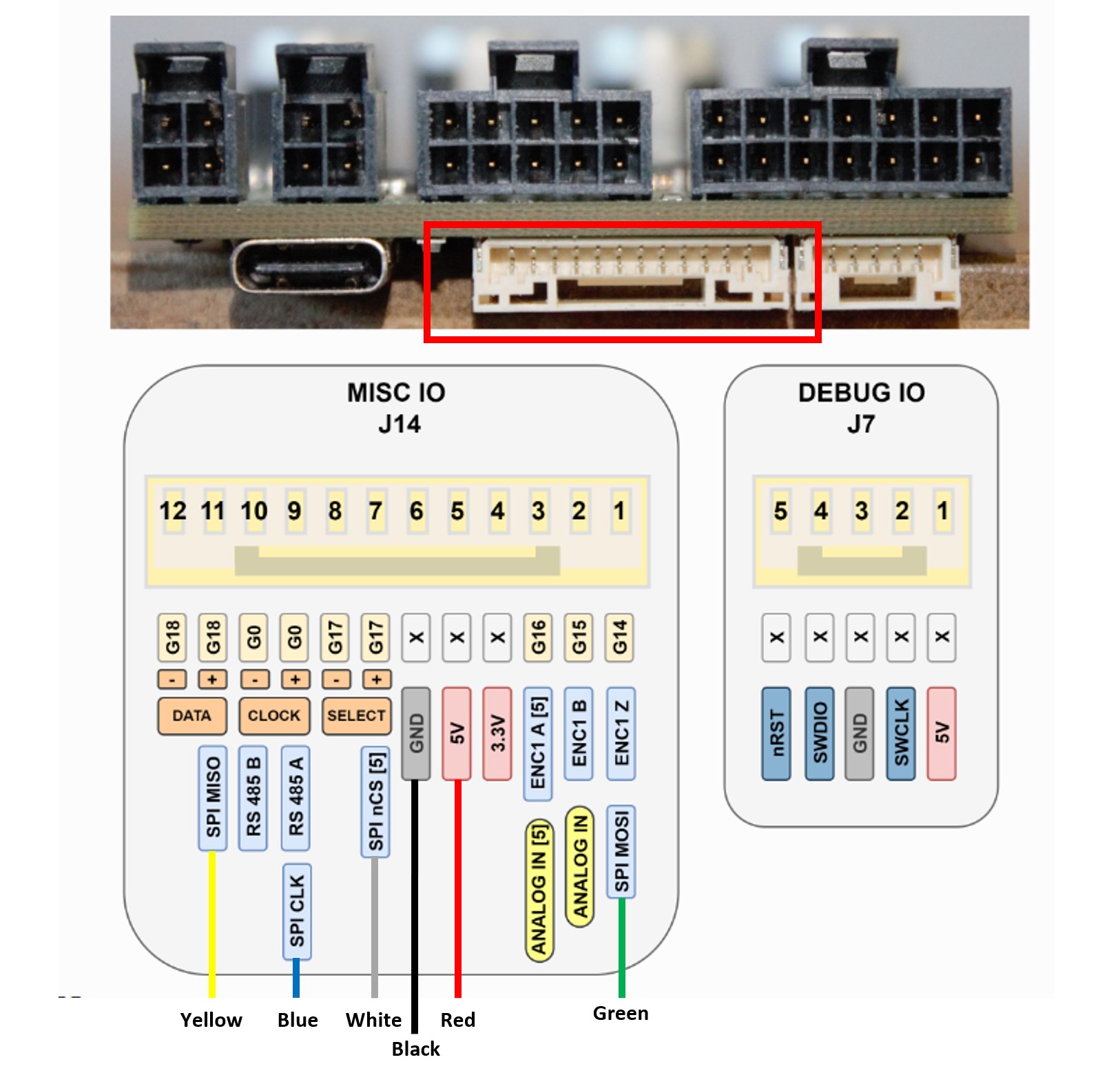
    Encoder Wiring Diagram

    GL60_Wiring

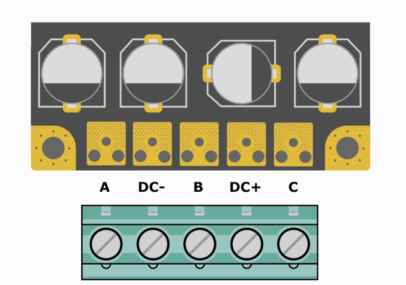
    3-Phase Motor and Power Cable Wiring Diagram

    Motor_Wiring
  • Connect the ODrive to the Host PC using USB-C cable.
  • Follow the Cabliration Instruction video and finish the motor configuration.

    Calibration Instruction Video


  • Set the below motor properties

    In "Power Source" page:
    DC bus overvoltage: 26
    DC bus undervoltage: 26
    DC max positive current: 5
    DC max nagative current: -5

    In "Motor" Setup page:
    Type: Gimbal
    Phase resistance : 1.2
    Pole pairs: 14
    KV: 55
    Current limit: 3.1
    Motor calib. current: 3.1
    Motor calib. voltage: 24
    Lock-in spin current: 0.1

    In "Encoder Paramater" page:
    Type: SPI(AMS protocol)
    nCS pin: GPIO17

    In "Control mode" page
    Control mode: Filtered Position Control
    Position Setpoint: USB/UART/CAN
    Bandwidth: 15
    Soft velocity limit: 10
    Hard velocity limit: 10
    Torque limit: 0.6

  • Go to the "Apply & Calibrate" page
    1) Click "Erase & Reboot" button in Erease old configuration step
    2) Click "Apply new configuration" button in Apply new configuration step
    3) Click "Save & Reboot" button in Save to non-volatile memory step
    4) Click "Run Calibration Sequence" button in Calibrate step and wait until calibration is done
    5) Click "Save & Reboot" button in Save to non-volatile memory step

  • Go to the Dashboard on the top of the page.
    Change the Position Gain, velocity Gain and velocity Integrator Gain as below.
    (This is the empirical value. You can find the better tuning values by modifying those.)
    Position Gain: 20
    Velocity Gain: 0.3
    Velocity Integrator Gain: 0.333

  • All electronic setup is completed. Go to the "Code" page and follow the instruction.

  • Design Instruction

    Assembly Time ~ 30-45 minutes


  • Before Assembly
  • Motor calibration is required before assebmling the BaRiFlex. Follow the "Electornic Instruction" first.
    Prepare all components (3D printed parts, Required Components, Other Misc. Parts and Tools) described below.

  • Main Assembly
  • Insert the 5 6mm bearings into the bearing holes on the Top and Bottom Housing.
    Insert the 6 6mm hex nuts into the hex nut holes in the Top Housing.
    Insert the 2 6mm shafts (41mm length) into both the Left and Right Crank gear holes leaving equal protruding shaft from the top and bottom of the crank.
    On the Left Rocker’s top holes, attach the bottom two holes of the Coupler Link using 1 M4 x 35 screw and secure the other end using an 4mm hex nut. Do not overtighten.
    Insert 1 torsion spring into the inside of the Coupler Link near the top.
    Insert the other end of the torsion spring into the left Finger Tip torsion spring hole.
    Align the mounting holes from the Finger Tip with the upper holes in the Left Rocker and the Coupler Link.
    Insert an M4 x 35 screw into the aligned holes and secure the end with a 4mm nylon lock nut. Do not over tighten.
    Insert the TPU Tip and TPU Finger extrusions into their designated holes on the Finger Tip.
    Apply grip tape along the face of the of the TPU Tip and TPU Finger
    Repeat steps 4-10 for the Right Crank.
    Insert 2 M6 x 40 screws into the bottom of the Bottom Housing and into the left and right lower rocker holes.
    Adjust the lower TPU Finger extrusions to overlap and sit between the two rocker screws.
    Over top the lower TPU Finger extrusions, and rocker screws, insert the Inner Link Stopper Spacer with the bare side facing up on the screws and facing the crank gears.

  • Actuator Drive Assembly
  • On the 6mm D-cut shaft (54mm length), in order, insert the Actuator Shaft Mounting Plate, 1 6mm flange (screwed into the plate), the pinion gear (geared side facing mounting plate) and 1 6mm flange (screwed into the pinion).
    All parts on the shaft should be up against each other but leave enough shaft protruding from both the top and bottom of the assembly to properly align the pinion gear with the crank gear.
    Screw the Actuator Shaft Mounting Plate to the actuator with 4 M3 x 8 screws.

  • Main Assembly (Cont.)
  • Insert the actuator drive assembly into the largest hole on the top housing.
    Making sure all shafts, bearings and screws align properly, and press the top and bottom housings together.
    Tighten the two rocker screws from the bottom of the bottom housing (Do not overtighten) and bring all the parts together making sure all shafts press into the bearings.
    Place the Motor Mount Case atop the actuator and align the 4 actuator holes with the holes on the case.
    Screw 4 M3 x 6mm into the 4 holes
    Align the extruding case holes with the extruding holes on the top housing and fasten them from the bottom using 2 M6 x 16 screws.
    Lastly, place the Flange Adapter between the top and bottom housings near the rear and run 2 M6 x 45 screws through from the bottom of the bottom housing and tighten until the screw reaches the case’s hex nut.